Bentopy: from simple packing to building cellular models
Tutorial authors: J.A. Stevens and M.S.S. Westendorp, with contributions from Bart M.H. Bruininks, C.M. Brown and W.J. Nauta.
In case of issues: Please contact m.s.s.westendorp@rug.nl or jaste@illinois.edu.
Summary
IntroductionProgramsTutorial 1: Basic Packing in Empty SpaceTutorial 2: Packing Around Existing StructuresTutorial 3: Multi-Compartment Systems with Placement RulesAdvanced Features and TipsReferences
The following video is a walkthrough of this tutorial.
Introduction
Bentopy is a tool for packing molecules in arbitrary volumes, designed specifically for setting up large-scale molecular dynamics (MD) simulations (Westendorp et al., 2026). Through an efficient packing algorithm, bentopy can assemble molecular structures into MD models with biological densities and cellular-scales.
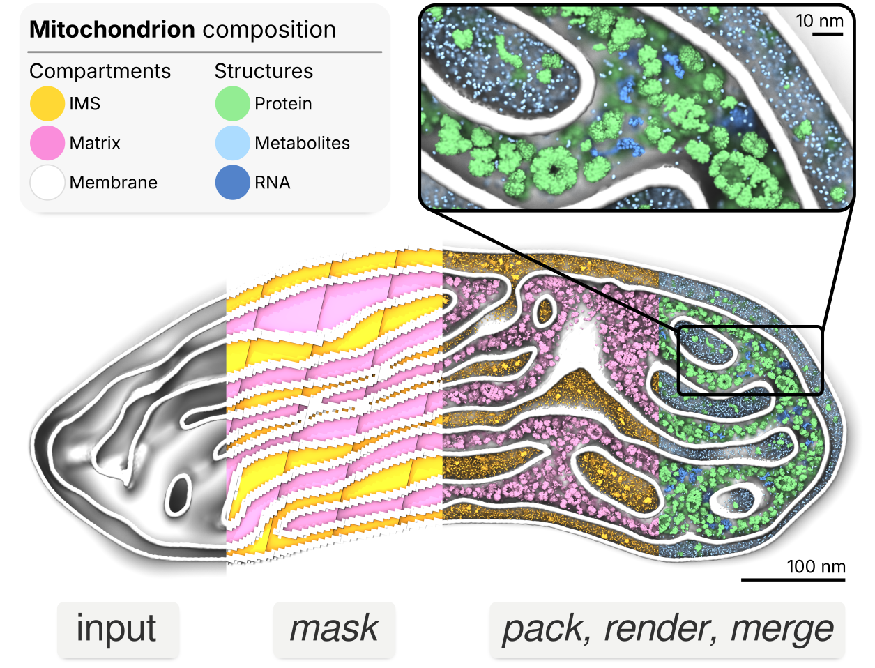
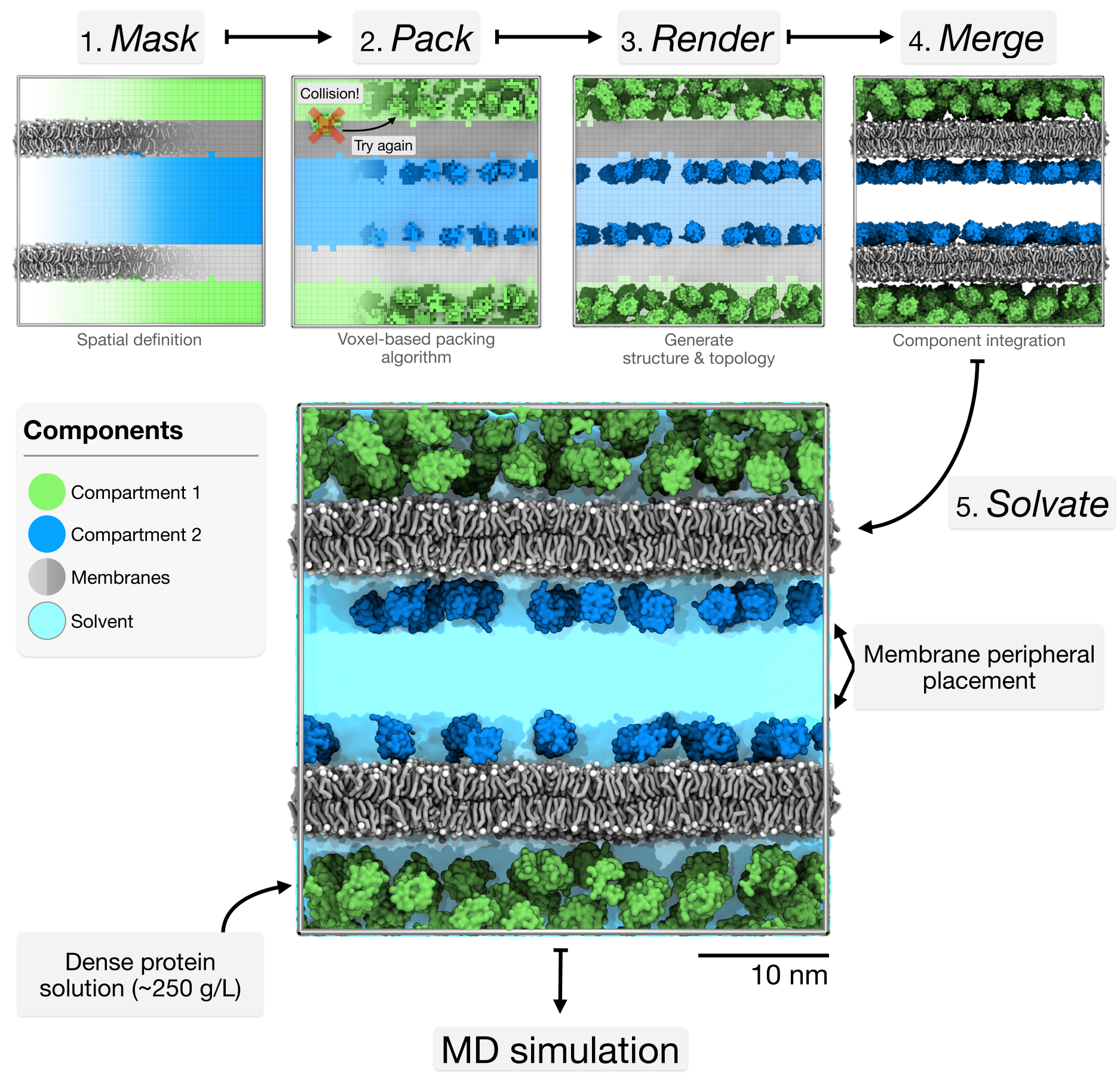
Bentopy was built to create cellular-scale models by integrating multiple structural components at physiological concentrations while ensuring simulation compatibility (Figure 2). Bentopy uses voxels to represent space as a regular 3D grid, providing computational efficiency for spatial operations like collision detection and informing molecule placement. For example, this voxel approach enables MDVContainment (Bruininks & Vattulainen, 2025) to automatically identify compartments within molecular models for packing, which is a central feature of bentopy.
In this tutorial, we will showcase bentopy’s capabilities through three progressively complex tutorials that build on each other (Figure 3).
- Simple packing: Learn the basic workflow by packing proteins in empty space.
- Packing around existing structures: Add a membrane and pack proteins around it.
- Multi-compartment systems: Add a second membrane creating distinct compartments for different proteins.
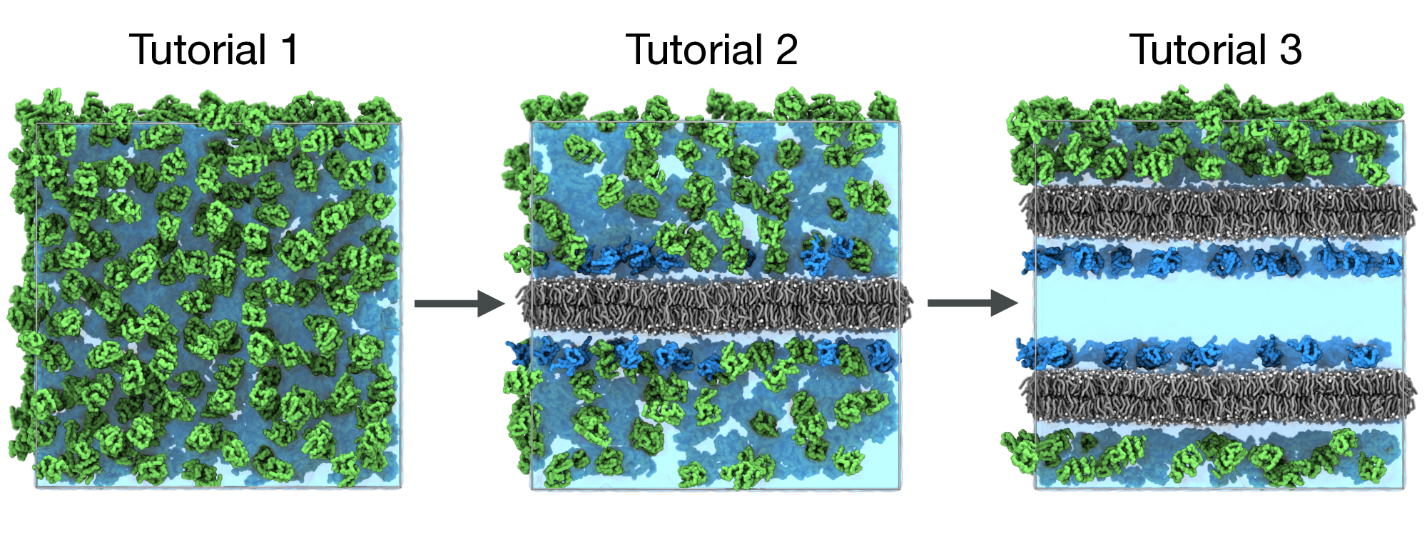
Each tutorial builds on the previous one, showing how to evolve a simple system into a complex model while using the standard bentopy workflow (Figure 7).
Programs and files
Installing bentopy
Bentopy is available through the PyPI. Pre-built binaries are available for some platforms. In most cases, you can use pip to install it without any prior steps.
pip install bentopyThis version of the tutorial was written for bentopy v1.0.0. If necessary, you can pin the version using
pip install bentopy==1.0.0.
If this installation fails at first, this may be because a pre-built binary is not available for your platform. To allow pip to build bentopy, cargo is required, which provides the Rust compiler.
You can try to see if it is already present on your system.
cargo --versionIf not present, install Rust through Rustup.
After installing Rust via rustup, you may need to reload your shell environment for the Rust tools (cargo, etc.) to be available in your PATH. Though you can reload your shell configuration by sourcing e.g., ~/.bashrc, opening a new terminal is most reliable.
You can verify whether the installation was successful by running cargo --version.
Now you can install bentopy directly via pip as described earlier.
Download tutorial files
Before starting the tutorial, download the required structure and parameter files. You download the tutorial files and extract them.
wget 'https://cgmartini-library.s3.ca-central-1.amazonaws.com/0_Tutorials/m3_tutorials/Bentopy/tutorial_files.tar.gz'
tar -xzf tutorial_files.tar.gz
cd tutorial_files
This archive contains structures, force field parameters, and simulation files.
structures/ |
Provided structure files: proteins (lysozyme.pdb, ubiquitin.pdb) and membranes (membrane.gro, double_membrane.gro) |
topology/ |
Martini force field files and protein topologies (lysozyme.itp, ubiquitin.itp) |
mdp_files/ |
Example Gromacs input files (em.mdp, eq.mdp, md.mdp) |
Other tools
- Standard command line tools.
- Visualization software:
VMD.
Tutorial 1: Basic Packing in Empty Space
Overview
We begin with the basic bentopy workflow by packing proteins into a simple cubic space. This tutorial introduces:
- The
.bentinput file. - Analytical mask definitions.
- The
bentopy-pack,bentopy-renderandbentopy-solvatecommands.
Create the packing configuration
Bentopy uses input configuration files to define packing parameters, called .bent files. These input files act as recipes for building different systems. They have a format that may be familiar to Gromacs users, but is also designed to be approachable and readable. Create a file called simple_packing.bent with the following contents.
simple_packing.bent
[ general ]
title "Proteins in a box"
seed 0

[ space ]
# All dimensions in bentopy are given in nanometers.
dimensions 40, 40, 40
resolution 0.5

[ includes ]
"topology/martini_v3.0.0.itp"
"topology/martini_v3.0.0_ions_v1.itp"
"topology/martini_v3.0.0_solvents_v1.itp"
"topology/lysozyme.itp"

[ compartments ]
system is all

[ segments ]
LYZ 650 from "structures/lysozyme.pdb" in system
Let’s discuss the key parts in this bentopy recipe.
- General section
- Sets general information, such as the system and a random seed.
- In this case, we use a defined seed to make sure that the results are repeatable. When the seed is not set, a random seed will be used at runtime.
- Space section
- Defines a 40×40×40 nm³ simulation box with 0.5 nm voxel resolution.
- Includes section
-
Specifies topology files for Gromacs compatibility. These files will be included when we generate the final topology with
bentopy-render. - Compartments section
- Defines the compartments that are available for placing segments.
- In this case, declare a compartment called “system”, which spans the entire space.
- Segments section
- Defines what structures are to be packed into what compartments and at what quantities.
- In this case, declare 650 lysozyme proteins to be randomly placed in the “system” compartment.
-
Note that the segment name “LYZ” refers to the name of the topology described in
topology/lysozyme.itp.
Pack the system
Now we can pack this system.
bentopy-pack simple_packing.bent placements.jsonThe output file placements.json contains all the placement information in a lightweight instance-based file format. We call this the placement list.
Render the structure
We can convert the placement list to a coordinate file.
bentopy-render placements.json system.gro -t topol.topThis creates system.gro with all protein coordinates and topol.top with the simulation topology.
Splitting the computationally intensive packing step from the process of writing out the entire coordinate file allows for more efficient workflows with large systems. This workflow also improves the shareability of models, as distributing the lightweight placement file is orders of magnitude more efficient than sharing the complete coordinate file.
Solvation
Finally, we add water and ions to complete the system preparation.
- 1
- Add 150 mM NaCl by substituting accepted water placements.
- 2
-
Neutralize the system charge by substituting additional ions. With the
neutraloption, the total system charge is automatically determined if a topology file is provided. This means that, on top of the ions substituted for the 150 mM NaCl, additional charge-neutralizing ions are added. - 3
- Append the solvent contents to the topology file.
We have now created a fully solvated system with 150 mM NaCl concentration and neutralized the system charge, ready for MD simulation.
bentopy-solvate is specifically designed and optimized for solvating large-scale models with millions or billions of particles, where traditional solvation tools become impractically slow. Yet, it is easy to use for more modest systems like this one as well.
Visualization and analysis
Open the system with VMD to inspect our current model.
vmd solvated_system.groThe result should be similar to the snapshot shown below, you can observe:
- The lysozyme proteins are distributed uniformly throughout the simulation box.
- The lysozyme proteins are packed at cytoplasmic densities. No overlap between proteins.

Try a different analytical mask
Learn how to use different shapes, such as spheres and cuboids, to construct compartments.
Before moving to the next tutorial, you can experiment a bit by trying a different analytical compartment shape. Simply replace the compartment definition in your simple_packing.bent file to pack proteins inside a sphere instead of the entire space.
simple_packing.bent
[ compartments ]
system as sphere at center with radius 20
Similarly, you can declare a space as a smaller cuboid as well.
simple_packing.bent
[ compartments ]
system as cuboid from 10, 10, 10 to 30, 30, 30Note that the available space to pack proteins has become smaller, so not all the requested proteins were placed. Bentopy indicated this with the remark ‘<’ in the packing summary that gets printed to your terminal. It’s advised to save this summary to a file as it contains all the relevant packing information for your project.
Output from bentopy-pack
Setting up compartments...
Loading segment structures...
Rearranging segments according to the Moment method... Done.
(  1/1) Attempting to pack   650 instances of segment 'LYZ'.
Packing process took 0.091 s.
idx     name           ok%  target  placed  time (s)    remark
----    ----------  ------  ------  ------  --------    ------
   0    LYZ          50.8%     650     330      0.09    <
                     50.8%     650     330      0.09    <
Writing placement list to "placements.json"... Done in 0.003 s.
Tutorial 2: Packing Around Existing Structures
Overview
In this tutorial, we will add a membrane. We treat this membrane as excluded volume, ensuring proteins are not placed within it. We will also introduce packing rules to place specific proteins close to the membrane surface. This tutorial introduces:
- Compartment definitions using voxel masks generated from existing structures.
- Proximity-based placement rules.
- The
bentopy-maskandbentopy-mergecommands.
Inspect the mask compartments
Before creating masks, it’s essential to understand what compartments bentopy identifies in your system. First, generate a visualization file to inspect the compartments identified in the voxel representation.
bentopy-mask structures/membrane.gro --visualize-labels labels.groThis automatically generates a structure file called labels.gro that contains a bead at every voxel position. Each voxel bead is named after the compartment it resides in. Visualize the voxel representation of our membrane system by opening the file with VMD.
vmd labels.groHere you can use the following atom selections to visualize the identified compartments:
- Solvent regions (“outside”, available for packing):
name "-1". - Membrane region (excluded from packing):
name 1.
The negative label (-1) typically represents the outermost compartment (solvent), while positive labels (1) represent inner or solid structures (membrane). Understanding these labels is important for selecting the correct compartments for protein placement.
Create the mask
Now that you understand the compartments, we will create the mask to guide our protein placement. Here, we create a mask called membrane_mask.npz from compartment 1.
bentopy-mask structures/membrane.gro -l 1:membrane_mask.npzA new recipe
Now we create a new bentopy recipe to use the membrane mask and include proximity rule. Create membrane_packing.bent as follows.
membrane_packing.bent
[ general ]
title "Proteins around a membrane"
seed 0

[ space ]
dimensions 40, 40, 40
resolution 0.5

[ includes ]
"topology/martini_v3.0.0.itp"
"topology/martini_v3.0.0_ions_v1.itp"
"topology/martini_v3.0.0_solvents_v1.itp"
"topology/martini_v3.0.0_phospholipids_v1.itp"
"topology/lysozyme.itp"
"topology/ubiquitin.itp"

[ compartments ]
1membrane from "membrane_mask.npz"
2solvent combines not membrane
3close-to-membrane around 5 of membrane

[ segments ]
4LYZ:lyz 300 from "structures/lysozyme.pdb" in solvent
5UBQ:ubq 100 from "structures/ubiquitin.pdb" in close-to-membrane
6# The part after the segment name is the optional tag (<name>:<tag>).- 1
- We load the mask from the file we created earlier.
- 2
-
We define the “solvent” region as the inverse (
not) of “membrane”, using a compartment combination. - 3
-
To create a compartment for the region around the “membrane” compartment, we use the
aroundrule. - 4
- Reduced total protein numbers (due to the membrane, there is less accessible space).
- 5
- Added ubiquitin with a proximity rule to stay within 5 nm of the membrane surface, but not including the membrane itself. See the Advanced Features section for more information on creating complex compartment combinations.
- 6
- Added a tag for each structure, which will override the resnames in each segment for easier visualization. These are particularly helpful in more complex models, where the same structure (same name) can be placed in different compartments at different quantities. Adding multiple segment definitions with different tags can be quite useful.
Using tags will override the original residue names in the gro file that bentopy outputs. While this makes visualization easier to inspect bentopy output (e.g., selecting all lysozyme with resname lyz), it may cause issues with analysis tools that expect standard residue names.
To instruct bentopy-render to ignore tag names, you can use the --ignore-tags flag.
Note that during MD simulation, Gromacs will automatically assign the correct chemical residue names based on the topology file, so simulation output will have proper residue naming.
Pack the system
Like before, we can now pack the system.
bentopy-pack membrane_packing.bent placements.jsonOrdering segments during placement
This is a short aside on how bentopy orders segments during packing.
Now that we have introduced another structure, we can consider how bentopy is supposed to order these. Generally, larger structures are harder to pack because they have fewer possible positions and orientations within the available space. Moreover, when small structures were already placed somewhere, they may obstruct the placement of a larger structure that could have been placed there, while the smaller structure could have been placed in many other locations.
By default, bentopy uses a ‘geometric moment’ heuristic (moment of inertia, taking all particles to have a unit mass) to rank different structures by how tricky they are to pack. Larger structures will be placed before smaller structures.
If desired, you can change this behavior to any of the available options. To do this, you can add a rearrange <method> line to the input file, or use the --rearrange <method> flag.
The available rearrange methods and heuristics are
moment: orders by geometric moment, default,volume: orders by molecular volumebounding-sphere: orders by bounding sphere radius, andnone: keeps the order specified in the input file.
In our testing, the moment method works best for most systems, but for specific use cases it may be worth experimenting with other options.
Render and merge
Convert the placement list to a coordinate file and combine the packed proteins with the membrane structure.
bentopy-render placements.json packed_proteins.gro -t topol.top

# Concatenate proteins with membrane structure
bentopy-merge packed_proteins.gro structures/membrane.gro -o system.gro
# Add lipid molecules to the topology file.
echo "POPC    5408" >> topol.top
The bentopy-merge command appends the structure files for the original membrane to the packed proteins.
Solvation
Add water and ions to complete the system preparation:
bentopy-solvate -i system.gro -o solvated_system.gro -t topol.top \
        -s NA:0.15M -s CL:0.15M --charge neutral
Visualization and analysis
Open the system with VMD to inspect the packing:
vmd solvated_system.groSince we used tags, you can now use the selections resname ubq and resname lyz in VMD to select the ubiquitin and lysozyme proteins respectively.
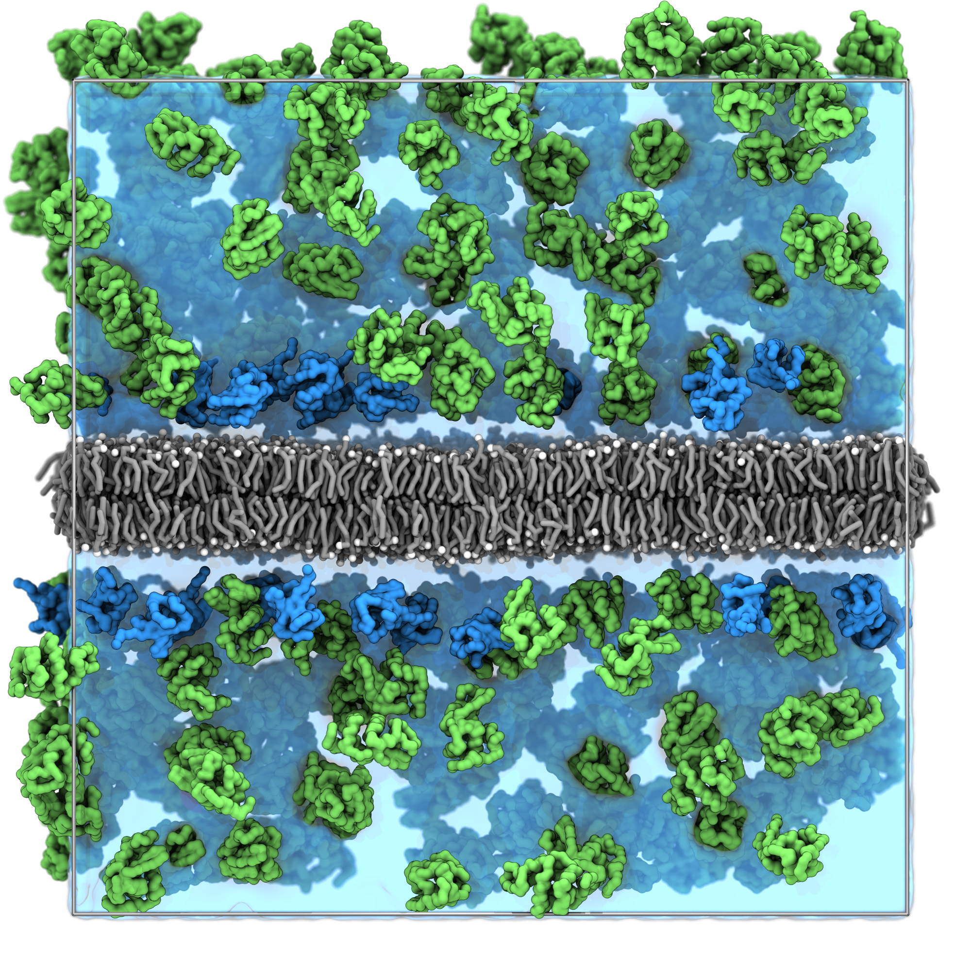
The result should be similar to the snapshot shown below, you can observe:
- The lysozyme proteins are distributed throughout the aqueous regions.
- The ubiquitin proteins concentrated near the membrane surfaces due to the proximity rule.
- No protein overlaps with the membrane structure.
Tutorial 3: Multi-Compartment Systems with Placement Rules
Overview
Now we’ll add even more complexity by creating a double membrane system that forms distinct compartments. Different proteins will be placed in different compartments. This tutorial demonstrates:
- Compartment-specific protein placement.
We’ll use the provided double membrane to create two distinct open compartments, then place different proteins in each compartment. Figure 7 contains a visual overview of how this system is constructed using the bentopy tools.
Inspect the double membrane structure
First, let’s examine the double membrane structure we’ll be working with:
vmd structures/double_membrane.groNotice how this system has two lipid bilayers, creating four distinct regions: two spaces between the two membranes, and the two membranes. We could conceive of one of the spaces between the membranes as being the “outside”, and take the other to be the “inside”. Under that view, this structure could represent a compartmentalised space similar to a vesicle or double-layer cell wall. However, the two inter-membrane spaces cannot be distinguished, due to the periodic nature of our box. Distinguishing outside and inside is therefore not entirely accurate. We’ll call them compartment A and B.
Create compartment-specific masks
Generate masks for the different compartments created by the double membrane like before. (We use the -b flag here which is short for --visualize-labels).
bentopy-mask structures/double_membrane.gro -b compartment_labels.groVisualize the voxel representation of our membrane system by opening the file with VMD.
vmd compartment_labels.groNow also double-check the different spatial compartments identified by the containment algorithm:
- Compartment A:
name "-1". - Compartment B:
name "-2". - Membrane regions (excluded):
name 1 2.
Create separate masks for each compartment
bentopy-mask structures/double_membrane.gro \
        -l  -1:A_mask.npz                   \
        -l  -2:B_mask.npz                   \
        -l 1,2:membrane_mask.npz
By adding multiple -l entries, we can write out all necessary mask files at once.
Update the configuration with compartments
Create a new configuration file compartment_packing.bent with multiple compartments and different protein compositions.
compartment_packing.bent
[ general ]
title "Proteins in different compartments"
seed 0

[ space ]
dimensions 40, 40, 40
resolution 0.5

[ includes ]
"topology/martini_v3.0.0.itp"
"topology/martini_v3.0.0_ions_v1.itp"
"topology/martini_v3.0.0_solvents_v1.itp"
"topology/martini_v3.0.0_phospholipids_v1.itp"
"topology/lysozyme.itp"
"topology/ubiquitin.itp"

[ compartments ]
membrane from "membrane_mask.npz"
1A from "A_mask.npz"
B from "B_mask.npz"
membrane-neighborhood around 4 of membrane
2B-close-to-membrane combines membrane-neighborhood and B

[ segments ]
3LYZ:lyz 200 from "structures/lysozyme.pdb" in A
4UBQ:ubq 100 from "structures/ubiquitin.pdb" in B-close-to-membrane- 1
- Added the A and B compartments.
- 2
- Created a compartment demonstrating how combinations can include boolean operations between previously defined compartments.
- 3
- Place lysozyme only in the A compartment.
- 4
- Place ubiquitin only in the B compartment and close to the membrane.
Pack the system
Pack our multi-compartment system.
bentopy-pack compartment_packing.bent placements.jsonRender and merge
Now we render and merge our structures like before.
bentopy-render placements.json packed_proteins.gro -t topol.top

# Merge proteins with membrane structure
bentopy-merge packed_proteins.gro structures/double_membrane.gro -o system.gro
echo "POPC    10816" >> topol.top  # Add lipid molecules to the topology file.
Solvation
Add water and ions to complete the system preparation.
bentopy-solvate -i system.gro -o solvated_system.gro -t topol.top \
        -s NA:0.15M -s CL:0.15M --charge neutral
Visualization and final analysis
We can now inspect our final system.
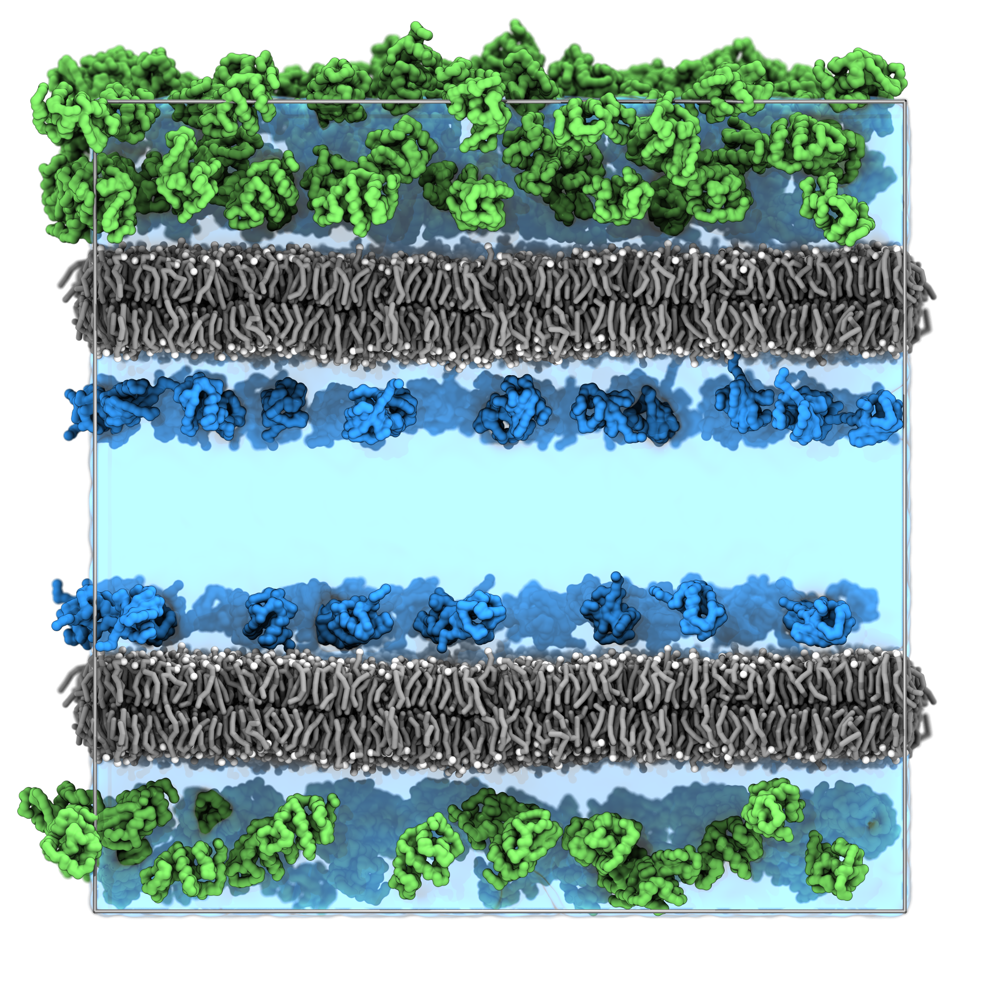
vmd solvated_system.groThe result should be similar to the snapshot shown below, you can observe:
- The lysozyme proteins are distributed throughout compartment A.
- The Ubiquitin proteins are concentrated near the membrane surfaces in compartment B.
- No protein overlaps with the membrane structure.
Run a simulation
With the complete solvated system, you can now run a molecular dynamics simulation using the provided input files.
# Energy minimization
gmx grompp -f mdp_files/em.mdp -c solvated_system.gro -p topol.top -o em.tpr
gmx mdrun -v -deffnm em

# Make index file
gmx make_ndx -f em.gro -o index.ndx << EOF
name 13 Lipid
r W | r ION
name 16 Solvent
q
EOF

# Equilibration
gmx grompp -f mdp_files/eq.mdp -c em.gro -p topol.top -o eq.tpr -n index.ndx
gmx mdrun -v -deffnm eq

# Production run
gmx grompp -f mdp_files/md.mdp -c eq.gro -p topol.top -o md.tpr -n index.ndx
gmx mdrun -v -deffnm md
You’ve now walked through the complete bentopy workflow from simple packing to a complex MD model!
Through these three tutorials, you’ve learned how bentopy can help you build complex molecular models with a well-structured workflow. This approach enables researchers to construct everything from crowded cytoplasm to whole-cell models with multiple compartments. The strength of bentopy lies in its ability to handle this complexity efficiently, making large-scale modeling accessible without sacrificing the molecular detail needed for accurate biological representation.
Advanced Features and Tips
For people who are interested in learning more about bentopy, the bentopy wiki is an excellent resource as well. This includes a reference document for the bent file format and some other example systems.
Solvation options
Bentopy includes bentopy-solvate, a solvation tool optimized for large-scale systems. For the complete documentation, see the bentopy-solvate README.
Ion substitutions with different quantities
# Molarity: 150 mM NaCl.
bentopy-solvate -i system.gro -o solvated.gro -s NA:0.15M -s CL:0.15M

# Fixed number: exactly 100 Na⁺ and 100 Cl⁻ ions.
bentopy-solvate -i system.gro -o solvated.gro -s NA:100 -s CL:100

# Ratio: replace 1% of water with Na⁺ ions.
bentopy-solvate -i system.gro -o solvated.gro -s NA:0.01
Set custom cutoff distances
For models with compartments, fine-tuning the number of water beads in the compartments is crucial for achieving a well-solvated model. The --cutoff flag controls the minimum distance between solvent and structure beads, allowing you to adjust the water bead placement. Increasing the cutoff creates more space around solutes (fewer water molecules), while decreasing it allows tighter packing (more water molecules). Additionally, the --solvent-cutoff flag is available to set the minimum allowable solvent–solvent distance over the periodic boundary conditions.
bentopy-solvate -i system.gro -o solvated.gro --cutoff 0.5 --solvent-cutoff 0.25All-atom waters
You can also use bentopy-solvate for atomistic models by setting --water-type tip3p. When you switch water types, the default solvent–structure collision distance updated too.
Render options for large systems
For large systems, bentopy-render provides several options to manage visualization and analysis:
Limiting render regions
Render only a specific region using --limits (format: minx,maxx,miny,maxy,minz,maxz):
# Render a 10×10×10 nm cube from (40,40,40) to (50,50,50)
bentopy-render placements.json small_region.gro --limits 40,50,40,50,40,50

# Render a thin slice in z-direction only
bentopy-render placements.json slice.gro --limits none,none,none,none,45,55
Reduced atom rendering
Use --mode to render fewer atoms for easier visualization:
# Render only alpha carbons
bentopy-render placements.json alpha_only.gro --mode alpha

# Render one bead per residue
bentopy-render placements.json residue_beads.gro --mode residue

# Render one bead per protein instance
bentopy-render placements.json instance_beads.gro --mode instanceReduced rendering modes cannot generate topology files, since these are only intended for visualization and validation. Use --mode full (default) when topology files are needed.
Residue numbering control
Control how residue numbers are assigned using --resnum-mode:
# Each protein instance gets unique residue number
bentopy-render placements.json system.gro --resnum-mode instance

# All instances of same protein type get same residue number
bentopy-render placements.json system.gro --resnum-mode segment
Residue name relabeling
Assign custom residue names when merging files for better organization and visualization:
# Assign custom residue names using the colon syntax.
bentopy-merge membrane.gro:MEM packed_proteins.gro:PROT -o complete_system.gro
bentopy-merge membrane.gro:MEM cytosol.gro:CYT chromosome.gro:CHR -o cell.gro
This allows easy selection and visualization of different system components in molecular viewers.
Configuration options
Example configuration for starting new projects
If you are starting a new project with bentopy, it may be helpful to have a jumping-off point for the configuration file. You can generate an example input file as follows.
bentopy-init example -o input.bentThis example lists and explains many of the available options with placeholders to be filled in with relevant values.
Convert legacy (.json) input files to the new format (.bent)
Early adopters of bentopy may still have .json input files. These can be converted to .bent files using bentopy-init.
bentopy-init convert -i input.json -o output.bentThis command can also be used to convert from .bent to .bent, in essence functioning as a formatter. Note that this will strip any comments.
Validate input files
Input configuration files can be checked for errors and potential problems using the validate subcommand.
bentopy-init validate -i input.bentFormatting .bent files
The parser for the input files is very flexible, allowing almost arbitrary whitespace between the keywords in any declaration. This may sound inconsequential, but it allows for formatting input files in ways that suit readability concerns or preferences.
For instance, long segment definitions can be neatly written over multiple lines.
[ segments ]
LYZ:lyz
    0.5mM
    from "long/structures/path/lysozyme.pdb"
    in long, list, of, compartments
    satisfies even, some, constraints
Using concentrations instead of fixed copy numbers
Instead of absolute copy numbers, it is also possible to provide molar concentrations (in mol/L).
[ segments ]
LYZ 5.0mM from "structures/lysozyme.pdb" in system
Controlling protein rotations
Constrain or set initial rotations for more realistic placement.
[ constraints ]
# Only rotate over the z-axis.
planar rotates z

[ segments ]
LYZ 50 from "structures/lysozyme.pdb" in system satisfies planar
The rotates constraint takes a comma-separated list of axes along which random rotations may be applied between different placements.
Compartment combinations
Create complex spaces using boolean operations on compartments.
[ compartments ]
a as sphere at  7.5, 10, 10 with radius 7.5
b as sphere at 12.5, 10, 10 with radius 7.5
c combines a and b
d combines not c
e combines a or not (b or d)
These combination expressions can be nested and combined again. The following syntax elements are available.
not <expr>-
Gives the inverse of
<expr>. <expr> and <expr>- Gives the intersection between two expressions.
<expr> or <expr>- Gives the union of two expressions.
( <expr> )- Group expressions.
Command line tips
Inspect placement lists:
Use jq to view placement files in a pretty-printed, readable format. Placement lists are not meant to be inspected directly, but it may be interesting to take a look. The placement list stores the translations and rotations for all instances of each segment. Also note that any important settings for reproducing a placement list, such as its seed, rearrange-method, or max-tries-mult are also stored in its header.
jq . placements.jsonTroubleshooting common issues
Packing failures
- Check bentopy’s packing summary output to see which segments failed.
- Use the
--verboseflag ofbentopy-packfor detailed information on the packing process. Double-check molecule counts/concentrations against available space. Use themax-tries-mult <number>declaration in the general section of the.bentfile to increase the number of placement attempts. The default value is 1000.
Mask problems
- Ensure mask dimensions match space dimensions ÷ resolution.
- Use the
-b(or--visualize-labels) flag ofbentopy-maskto output agrovisualization file for the voxel representation of the identified compartments. - Try different containment/mask resolutions if too many compartments are identified.
- The
--morphflag can be used to ‘repair’ holes that might undesirably connect seperate compartments, even at finer containment resolutions. By default, it has the valuede, which means ‘dilate then erode’. This is equivalent to a morphological closing operation. - Morphing can be disabled entirely using the
--no-morphflag.
Rendering errors
- Verify all structure paths in placement list are accessible. If you are rendering in a different location than where the packing took place, the
--root <path>option may be helpful. It sets the location from where the input structure paths will be resolved. - Check structure file formats (
pdbandgrofiles are supported for input structures).
Topology issues
- Ensure segment names in the
.bentfile match molecule names in the.itpfiles. Use tags to distinguish different segments of the same structure. - Verify all
.itpfiles listed intopol_includesexist and contain the expected topology information.
For additional support, examples, and updates, visit the bentopy GitHub repository.